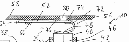
The application relates to a heat exchanger arrangement with a sensor (40) in a sensor receiving opening (42), wherein the sensor is supported on an inner wall (30) by a biasing member (52) arranged between the sensor (40) and a biasing member abutment region (74) provided on the outer housing (58).

Brief outline of the case
The application was refused for lack of IS with D2 as CPA.
The decision of the ED was set aside and the case remitted with the order to grant a patent.
The case is interesting as it deals with the correct definition of the objective technical problem (OTP).
Disclosure of Fig 1 of D2
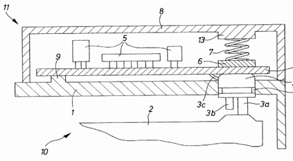
D2 (see in particular Figure 1) is indisputably a suitable starting point for assessing IS, since a heat exchanger arrangement is also disclosed, in which a temperature sensor (3) with a biasing member is supported in a fluid-tight manner in an opening of an inner wall (“housing jacket 1”) so as to be displaceable against this inner wall.
A projection 13 is provided on the outer housing (8) opposite the sensor opening to support the biasing element. The support of the spiral spring between the abutment area and the sensor forms a loading area.
In contrast to claim 1 of the MR, in D2 a spiral spring is used as the biasing member, which is fixed at its one end within the biasing member abutment region (13) on the outer housing (8) (see paragraph [0038]: “fitting recess … for the positive-
The subject-matter of claim 1 of the MR therefore differs from the disclosure of D2 by the following features:
a) The pre-tensioning member is designed in the form of a leaf spring.
b) This leaf-spring-like pre-tensioning member has a fixing region and a loading region in respective other end regions.
c) The loading region provided in the first end region is U-shaped, the U-shaped design being such that a first U-leg is supported with respect to the biasing member abutment region and a second U-leg is supported with respect to the opposite end.
d) The fixing area provided in the other end area serves to fix the pre-tensioning element to the outer housing.
Features b) to d) define two distinct end regions of the leaf spring-like pre-tensioning element with different functions
The fixing area is not located in the area of the biasing element abutment area or sensor, but at an “other end“, which must be separable from the loading area and in which the biasing element is fixed to the outer housing
Objective technical problem for the ED
In the contested decision, the ED concluded that the OTP is to “provide an alternative way of applying force to the sensor”.
This problem appears to be based on the consideration that a U-shaped leaf spring is an alternative to the spiral spring used in D2.
Objective technical problem for the board
The board did not agree with this OTP, as it takes into account at most the distinguishing features a) (leaf spring-like) and c) (U-shaped), but not the distinction between the ends of the biasing element in a respective distinct impact area and fixing area according to the distinguishing features b) and d).
In the present case, the distinguishing features a) to d) interact functionally and must therefore be taken into account when determining the OTP.
The interaction is such that the biasing force acts directly through the U-region of the leaf-spring-like biasing element on the opposite support region, so that significant reaction forces stressing the fixing region due to the loading of the sensor are avoided.
In particular, the spatial separation of the fixing and loading areas prevents tilting moments from the loading area from enabling the preload element to be fixed outside the loading area without the preload force acting in the loading area transmitting a significant torque to the fixing area.
This solution is independent of the type of fixation in the fixing area; various alternatives are disclosed in the application with regard to the fixation.
In D2, although no tilting moments act on the fixing area of the spiral spring, reaction forces nevertheless act on the fixing area due to the compression of the spring when the sensor is loaded.
With regard to the interdependency of the distinguishing features, the OTP is therefore to avoid significant reaction forces that stress the fixing area due to the impact on the sensor.
Inventive step given
The contested decision does not convincingly show why the skilled person would arrive at a leaf-spring–like pre-tensioning element designed and installed in accordance with features b) to d) by means of routine design work.
It is already questionable whether the provision of a U-shaped leaf spring between the support areas instead of the spiral spring is suggested by common general knowledge. The contested decision does not provide any evidence in this regard
D1 has a specific solution in a single patent specification and cannot demonstrate common general knowledge.
However, even if one follows the reasoning in the contested decision, according to which a U-shaped leaf spring is one of several obvious spring designs, features b) and d) do not follow directly from the selection of a U-shaped leaf spring as an alternative to the spiral spring in D2.
Comments
The present decision reminds us to have a very specific look at the differences between the CPA and the claimed subject-matter.
It can be agreed that, broadly speaking, using a leaf spring instead of a compression spring can represents an alternative solution. However, the way the leaf spring is fixed cannot simply be swept under the carpet.
The present decision also reminds us that a patent document is not representative of common general knowledge.
https://www.epo.org/de/boards-of-appeal/decisions/t210241du1
Comments
Leave a comment